Understanding the Injection Molding Machine: A Comprehensive Diagram Analysis
The injection molding machine is the cornerstone of mass-producing plastic parts with high precision and repeatability. To fully understand its operation, one must refer to its schematic diagram, which visually maps the interaction between mechanical, hydraulic, and electrical systems. This article provides a detailed breakdown of a standard injection molding machine diagram, explaining the function and interplay of its core components.
1. The Two Primary Units: Clamping and Injection
Every injection molding machine diagram fundamentally separates the system into two main assemblies: the Clamping Unit and the Injection Unit. These units perform distinct phases of the molding cycle.
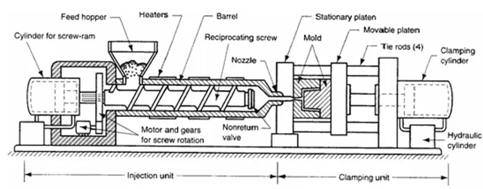
1.1 The Clamping Unit
Located typically on the left side of the diagram, the clamping unit is responsible for opening, closing, and holding the mold under immense pressure during injection and cooling. Its key components include:
- Stationary Platen: The fixed plate to which one half of the mold is bolted.
- Moving Platen: The plate that moves along the tie bars, carrying the other mold half.
- Tie Bars: Four large rods that guide the moving platen and absorb the clamping force.
- Clamping Cylinder: A hydraulic (or toggle) mechanism that generates the force to keep the mold closed against injection pressure.
- Ejector System: Mechanism (hydraulic or mechanical) that pushes the finished part out of the mold after cooling.
1.2 The Injection Unit
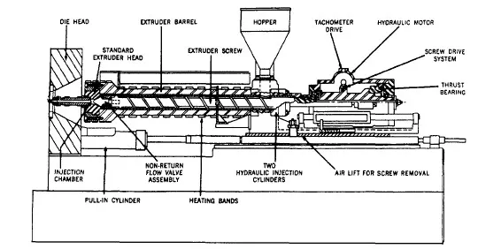
Mounted on the right side, the injection unit's role is to plasticize (melt) the raw material and inject it into the mold cavity. Its primary elements are:
- Hopper: The container that holds the plastic resin pellets.
- Barrel: A heated cylinder containing a reciprocating screw.
- Reciprocating Screw: The core component that rotates to melt and mix the plastic, then moves forward as a plunger to inject the melt.
- Heater Bands: External heating elements arranged along the barrel to provide precise temperature control.
- Nozzle: The tip that seals against the mold's sprue bushing to allow melt passage.
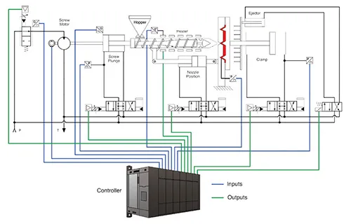
2. The Hydraulic and Control Systems
The diagram also illustrates the supporting systems that power and regulate the machine's movements.
2.1 Hydraulic Power System
This system provides the necessary force and motion for clamping, injection, and ejection. Key parts shown include:
| Component | Function |
|---|---|
| Hydraulic Pump | Generates fluid flow and pressure for the entire system. |
| Directional Control Valves | Direct hydraulic fluid to specific actuators (cylinders, motors). |
| Hydraulic Cylinders | Convert fluid pressure into linear motion (e.g., for clamp movement, screw injection). |
| Accumulator | Stores hydraulic energy for high-demand, rapid actions like fast clamp closing or high-speed injection. |
2.2 Control System
Represented by electrical symbols and connections, the control system is the machine's brain. It encompasses:
- Programmable Logic Controller (PLC): Executes the sequential logic of the molding cycle.
- Temperature Controllers: Maintain precise heat profiles in the barrel and mold.
- Pressure & Speed Sensors: Provide feedback for precise control over injection and holding phases.
- Operator Interface (HMI): The touchscreen panel for setting parameters and monitoring machine status.
3. The Molding Cycle as Depicted in the Diagram
The diagram allows us to trace the step-by-step process of the injection molding cycle:
- Clamping: The hydraulic cylinder moves the moving platen to close and lock the mold.
- Injection: The screw moves forward, injecting the molten plastic through the nozzle into the sealed mold cavity.
- Holding & Cooling: Pressure is maintained to compensate for material shrinkage as the part cools and solidifies.
- Plasticizing: While the part cools, the screw rotates, retreating to feed and melt the next shot of material.
- Ejection: The mold opens, and the ejector system advances to push the finished part out.
Conclusion
An injection molding machine diagram is more than just an illustration; it is a vital tool for understanding the machine's complex operation, troubleshooting issues, and optimizing the manufacturing process. By dissecting the diagram into its core units—clamping, injection, hydraulic, and control—engineers and operators can gain a profound insight into the synchronized dance of mechanics and electronics that produces the plastic components essential to modern life.