Understanding Thermoforming Machine Diagrams: A Comprehensive Guide
Thermoforming is a versatile manufacturing process used to shape plastic sheets into specific forms. At the heart of this process lies the thermoforming machine, a complex piece of equipment whose functionality is best understood through its schematic diagram. This diagram is not just a drawing; it's a blueprint that reveals the intricate interplay of mechanical, thermal, and control systems working in unison to transform a flat plastic sheet into a finished product. From packaging and automotive parts to consumer goods, understanding the thermoforming machine diagram is crucial for operators, engineers, and anyone involved in plastics manufacturing.
Core Components of a Thermoforming Machine
A standard thermoforming machine diagram can be broken down into several key subsystems. Each plays a vital role in the sequential process of heating, forming, and trimming the plastic.
1. The Material Handling and Clamping System
This is the starting point of the process. A roll of plastic sheet (roll-fed) or individual sheets (cut-sheet) is loaded into the machine. The clamping system, consisting of strong frames and clamping bars, securely grips the perimeter of the plastic sheet. This ensures the sheet remains taut and in a fixed position throughout the heating and forming stages, preventing wrinkles or misalignment.
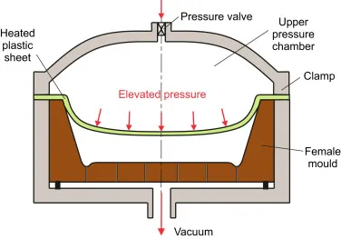
Figure 1: A detailed view of the clamping frame mechanism, showing the upper and lower platens that secure the plastic sheet.
2. The Heating Oven
Perhaps the most critical stage, the heating oven softens the plastic sheet until it reaches its forming temperature—a pliable, rubbery state. The diagram typically shows an array of heating elements, often ceramic or quartz infrared heaters, positioned above and below the sheet. These elements are divided into zones, allowing for precise control of the heat profile across the sheet to ensure even heating, which is crucial for consistent wall thickness in the final product.
3. The Forming Station
Once heated, the plastic sheet is quickly transferred to the forming station. Here, the actual shaping occurs. The diagram illustrates two primary methods:
- Vacuum Forming: A mold is raised into the soft plastic sheet, and a powerful vacuum is applied through tiny holes in the mold, sucking the air out and pulling the plastic tightly onto the mold's contours.
- Pressure Forming: In addition to vacuum from below, pressurized air is applied from above, forcing the sheet onto the mold with greater detail and sharper definition.
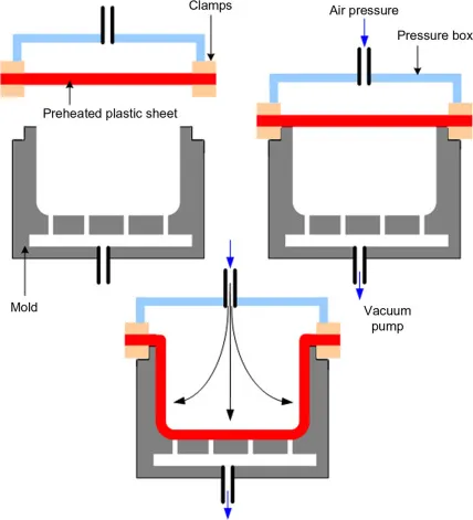
Figure 2: Cross-section of a forming station, highlighting the mold, vacuum box, and the path of the vacuum pressure.
4. The Mold and Plug Assist
The mold is the negative of the desired final part. Diagrams often detail the mold's construction, which can be made from aluminum, wood, or composite materials. For deeper draws, a "plug assist"—a mechanical aid that pre-stretches the hot plastic into the mold cavity—is used to achieve a more uniform material distribution.
5. The Cooling and Trimming System
After forming, the plastic part must be cooled while still on the mold to solidify its new shape. The diagram shows cooling channels within the mold through which water or air is circulated. Once cooled, the part is released from the mold. In an in-line machine, the formed sheet then moves to a trimming station where a die cutter punches out the individual parts from the web of plastic, which is then wound up as scrap for recycling.
6. The Control System
Overseeing the entire operation is the Programmable Logic Controller (PLC). The machine diagram will include symbols for sensors, actuators, and the central control unit. This system automates the timing and sequencing of every step—clamping, heating time, oven temperature, forming cycle, and cooling time—ensuring repeatability and precision.
Process Parameters Table
| Process Stage | Key Parameters | Typical Values / Considerations |
|---|---|---|
| Heating | Heater Temperature, Heating Time, Zone Control | 300-600°C, 10-60 seconds, adjusted for sheet thickness and material type (e.g., PS, PET, PP). |
| Forming | Vacuum/Pressure Level, Forming Time, Mold Temperature | Vacuum: > 25 Hg, Pressure: 50-100 psi. Time: 2-10 seconds. Mold temp: 60-80°F for quick cycle times. |
| Cooling | Cooling Time, Coolant Temperature | 5-15 seconds. Chilled water at 10-15°C is often used for efficient heat transfer. |
Types of Thermoforming Machines and Their Diagrams
The basic principles remain the same, but machine configurations differ, which is reflected in their diagrams.
In-Line Thermoforming Machines
These machines feature a linear flow: the sheet is loaded on one end, and finished, trimmed parts exit from the other. The diagram shows distinct, separate stations for loading, heating, forming, cooling, and trimming arranged in a straight line. This design is ideal for high-volume production runs.
Rotary Thermoforming Machines
In a rotary machine, the clamping frame is mounted on a rotating carousel that indexes the sheet between two or more stations. A common setup has three stations: load/offload, heating, and forming. This design allows for simultaneous operations (e.g., heating one sheet while forming another), significantly increasing production speed for certain applications.
Figure 3: Overhead schematic of a rotary machine, illustrating the circular path of the clamping frames between stations.
Conclusion: The Diagram as a Essential Tool
A thermoforming machine diagram is far more than an assembly guide. It is an essential tool for troubleshooting, optimizing the process, and training personnel. By understanding the function and interconnection of each component represented in the diagram, operators can diagnose issues like uneven heating, poor part definition, or webbing. Engineers can use it to model process improvements and ensure machine safety. In essence, mastering the thermoforming machine diagram is the first step toward mastering the art and science of thermoforming itself, enabling the efficient and high-quality production of the plastic products we use every day.